Roughing is often where CNC cycle time hides. A pocket that looks simple on the drawing can become a long sequence of heavy cuts, cautious feed rates and heat management problems once it reaches the machine. High efficiency milling, often shortened to HEM, tackles that problem by keeping cutter engagement under control while increasing feed rate and axial depth of cut.
The result can be dramatic. A Modern Machine Shop article on high efficiency milling techniques notes that roughing cycle times can be reduced by as much as 80% in some applications, although often only for certain part features.
Still, that explains why high efficiency milling has become a go-to HEM machining strategy for shops trying to reduce roughing cycle time on CNC machines. When the part, machine, workholding, cutter and CAM strategy are a good fit, HEM can remove material faster while putting less concentrated stress into the tool.
What is high efficiency milling?
HEM is a roughing strategy that uses a light radial depth of cut, a heavier axial depth of cut and a higher feed rate than many conventional roughing approaches. Put simply, the cutter takes a narrower bite sideways, cuts deeper along its length and moves faster through the material.
That combination matters because it spreads heat and wear across more of the cutting edge. Machining Doctor explains that milling depth of cut has two dimensions: radial depth of cut, which is the engagement perpendicular to the tool axis, and axial depth of cut, which is the engagement along the tool axis. In HEM, the balance shifts towards lighter radial engagement and deeper axial engagement.
The key terms are:
- Radial depth of cut, or RDOC: how far the tool steps over sideways into the material.
- Axial depth of cut, or ADOC: how deep the tool engages along its centreline.
- Chip load: the thickness of material removed by each tooth.
- Engagement angle: how much of the cutter is in contact with the workpiece at any point.
In heavy conventional roughing, it is common to use a large stepover and a shallower axial cut. In HEM, the radial cut is reduced and the axial cut is increased. Kennametal describes its dynamic milling end mills as designed for low radial engagement and full length of cut, which captures the basic mechanical idea behind the strategy.
The aim is to keep cutting forces more predictable, use more of the flute length and avoid sudden tool load spikes. That is why HEM is often described as a constant-engagement approach. The goal is to stop the cutter being heavily loaded in one area, especially in corners, slots and pockets where engagement can rise quickly.
Academic work supports that principle. Research on trochoidal-like tool path planning describes constant engagement angle as a way to improve high-efficiency milling stability, particularly where changing cutter engagement can create chatter or inefficient cutting.
The numbers: how HEM cuts roughing time
The headline number for HEM is roughing cycle time reduction. In the right application, the gains come from three effects working together.
First, a small stepover reduces radial cutting force. The tool is less buried in the material, so it can move faster without being overloaded. Second, a deeper axial cut uses more of the flute length, which spreads wear across the cutter instead of concentrating it near the tool tip. Third, radial chip thinning allows the programmed feed per tooth to increase while maintaining a proper chip thickness.
That is how HEM can remove more material per minute without simply forcing the tool harder through the cut. Instead of taking a wide, slow bite, the cutter takes a narrow, controlled bite at higher feed and greater depth.
A simple example shows why the total job saving depends on the part. Suppose a part has 40 minutes of roughing, 10 minutes of finishing and 5 minutes of tool changes, probing and handling. If HEM cuts roughing time by 60%, the total cycle falls from 55 minutes to 31 minutes. If roughing time falls by 80%, the total cycle falls to 23 minutes.
That is still a major saving, but it also shows why “80% faster roughing” and “80% faster total part cycle” are different claims. HEM has the biggest impact when roughing is a large share of the programme, material removal is high and the machine, workholding and tooling can support the strategy.
Trochoidal milling explained
Trochoidal milling is one of the best-known HEM toolpath styles. Instead of slotting straight through material with the full cutter width engaged, the tool moves in a series of looping or circular arcs. Each arc removes a controlled amount of material, then the cutter advances and repeats the motion.
This keeps radial engagement low and helps maintain a more consistent chip load. It is especially useful when cutting slots, opening pockets, machining tight internal corners or working with harder materials where full-width engagement would create too much heat and force.
Seco Tools describes trochoidal milling as a spiral toolpath strategy that uses low radial depth of cut and high axial depth of cut to cut slots wider than the tool diameter. Seco also lists radial chip thinning, faster feed rates, improved accuracy and longer tool life among its advantages.
Trochoidal milling can improve tool life and process stability as well as speed. The cutter is rarely buried in the cut. The tool spends less time at high engagement, chips can evacuate more easily and the programme can avoid sudden load spikes.
Iscar also highlights trochoidal milling as effective for deep slots, pockets and cavities, and as a promising method for difficult-to-cut materials such as titanium and high-temperature superalloys.
Good use cases include:
- Deep slots where full-width cutting would overload the tool.
- Pockets with tight corners where engagement rises quickly.
- Aerospace, medical and mould components with high material removal.
- Tough materials such as stainless steel, titanium and nickel alloys.
- Long-reach tools where deflection control matters.
It is less useful when the part has very shallow roughing, weak workholding, low machine acceleration or features where the extra path length outweighs the benefit of higher feed.
5 HEM strategies you can use today
Start with light radial engagement
The first practical step is to reduce stepover. Many HEM toolpaths use a small percentage of the cutter diameter radially, then increase axial depth and feed rate to raise material removal rate.
As a practical benchmark, Sandvik Coromant advises that maximum radial depth of cut in trochoidal milling should not exceed 20% of cutter diameter. The exact value depends on tool diameter, flute count, material, machine power, tool stickout and coolant strategy.
A lighter radial cut reduces side load, but it also changes the relationship between programmed feed per tooth and actual chip thickness. That leads directly to the next strategy.
Account for radial chip thinning
When radial engagement drops, the chip becomes thinner than the programmed feed per tooth might suggest. If the feed is not adjusted, the tool can rub instead of cutting cleanly. That creates heat, poor finish and premature wear.
WIDIA explains that when radial width of cut is 40% or less, average chip thickness reduces and feed rate must be increased to compensate. This is one of the most important details in HEM machining strategy, because a light radial cut only works properly when the chip thickness is right.
Machining Doctor’s chip thinning guide describes the same underlying issue: when radial depth of cut is smaller than the cutter radius, chip load is smaller than feed per tooth. In practical terms, a low stepover does not automatically mean the cutter is cutting correctly. It may be rubbing unless the feed has been set for the real chip thickness.
For programmers, the practical takeaway is simple: do not copy a conventional feed rate into an HEM toolpath. Use tooling data, a chip thinning calculator, CAM feed guidance and a safe prove-out process.
Use more of the flute length
HEM is designed to use deeper axial cuts. Instead of wearing out the end of the cutter, the strategy spreads the load along more of the cutting edge. In the right setup, this can increase material removal while improving tool life.
That does not mean every job should run at the maximum flute length. Tool projection, holder rigidity, machine condition and part setup all matter. For long-reach tools, reduce aggressiveness and watch for chatter. For shorter, rigid setups, deeper axial engagement is where HEM often delivers its strongest roughing gains.
The principle is simple: if the cutter can safely use more of its cutting edge, the shop may reduce the number of stepdowns, spread heat across a longer flute length and remove more material per pass.
Choose the right cutter
A general-purpose end mill may work for light trials, but HEM rewards tooling designed for the strategy. Look for solid carbide end mills with strong core geometry, appropriate flute count, good chip clearance, variable helix or variable pitch design and a coating suited to the material.
For steels and harder alloys, higher flute counts can support the lighter chip load and higher feed style used in HEM. For aluminium, fewer flutes and strong chip evacuation are usually more important.
Tool choice should reflect the whole setup. Kennametal’s dynamic milling cutter guidance points to features such as chip management, internal coolant options and material-specific flute forms. Those details matter because HEM often produces many thin chips at high feed rates.
A short, rigid cutter in a stable holder can usually support more aggressive axial engagement than a long-reach tool. A machine with limited acceleration may also struggle to maintain smooth motion through small arcs and direction changes, even if spindle power looks adequate on paper.
Manage chips and heat
HEM depends on clean chip evacuation. Recirculating chips can damage the cutting edge, mar the surface and increase tool load. Air blast, through-tool coolant or high-pressure coolant may be needed depending on the material and cutter.
For aluminium, the priority is often clearing chips and preventing built-up edge. For steels and heat-resistant alloys, coolant strategy depends on tooling, coating and cutting data. Follow tool supplier guidance, then validate on the machine using spindle load, sound, chip colour, tool wear and part finish.
Chip evacuation is especially important in deep pockets and slots. In those features, chips can stay trapped near the cutter and turn a stable HEM strategy into an unstable one. If the machine sound changes, spindle load rises or chips begin packing into the cut, reduce the aggressiveness and fix chip clearance before increasing feed again.
How CAM software makes HEM practical
The challenge with high efficiency milling is that the idea is simple but the programming can be complex. A good HEM toolpath needs to control engagement through corners, avoid sudden cutter load, manage entry and exit moves, maintain chip thickness and keep air cutting to a minimum.
That is hard to do manually on anything beyond simple geometry. Modern CAM systems help by calculating toolpaths that reduce engagement spikes and adjust motion through corners and narrow features.
Autodesk’s Adaptive Clearing documentation explains that the strategy maintains constant engagement between the tool and surrounding material, while using cuts that minimise abrupt direction changes. Autodesk notes that this can reduce the possibility of tool breakage and improve tool life.
Mastercam’s Dynamic Motion page describes a similar approach based on engagement machining principles, smaller stepovers and consistent chip thickness. Mastercam states that these toolpaths can support higher feed rates and produce faster roughing and pocketing cycles in real-world applications.
Siemens NX CAM also describes 3D Adaptive Roughing as a high-performance cutting strategy that enables deep cuts and consistent tool load, with cycle-time reductions of up to 60% in hard-material applications.
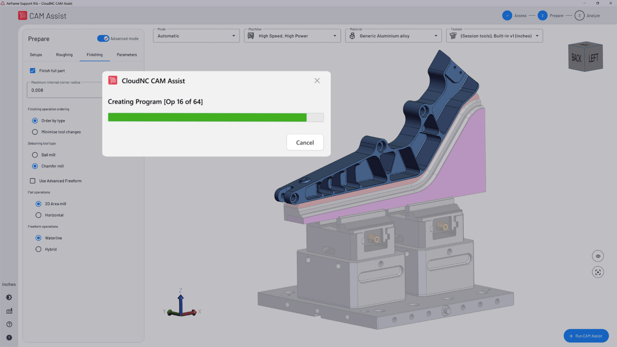
This is also where AI CAM tools can support programmers as they evaluate machining strategies more quickly. CAM Assist helps generate machining strategies and toolpaths inside existing CAM workflows, while leaving programmers to review and adjust before sending work to the machine.
The key point is control. HEM should still be simulated, checked against workholding, proven out safely and adjusted for the real machine. The software can help create a strong starting point, but machinist judgement remains central.
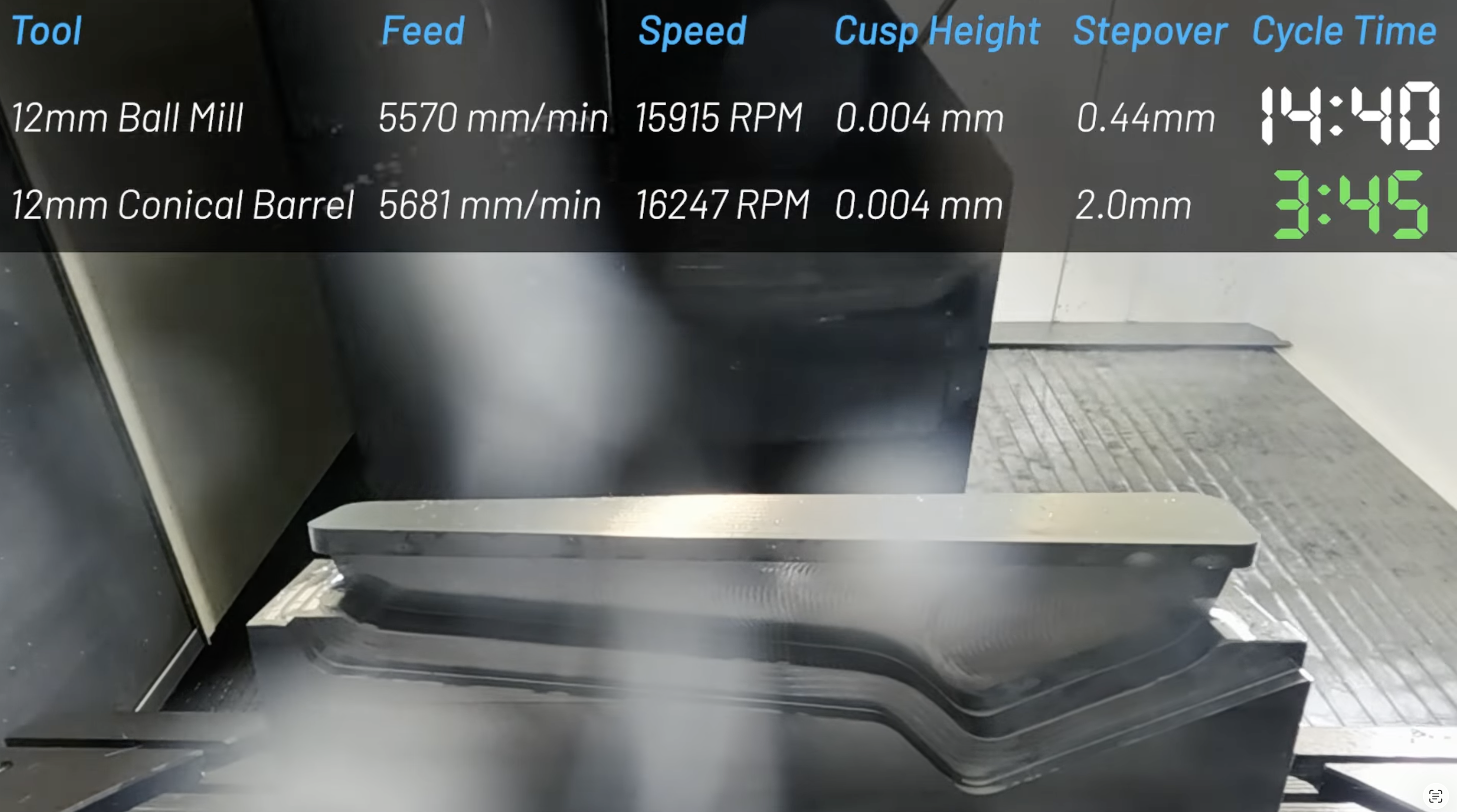
Here's a video of some advanced techniques we use on complex aerospace parts with freeform elements at our Chelmsford factory:
Common HEM mistakes and how to avoid them
Using too much stepover
The most common mistake is treating HEM like conventional roughing with a faster feed rate. If radial engagement is too high, cutting forces rise quickly and the tool loses the stability that makes HEM work. Start conservatively, then increase only when chip formation, tool wear and spindle load look stable.
Ignoring chip thinning
Small stepovers need feed compensation. Without it, the tool may rub, generate heat and fail early. This can make a programme look safe on paper while performing badly on the machine.
Picking the wrong tool geometry
A cutter with poor chip evacuation, excessive stickout or the wrong flute count can limit the whole strategy. Match the cutter to the material, pocket depth, radial engagement and coolant approach.
Running weak setups too aggressively
HEM reduces radial cutting force, but it does not remove the need for rigidity. Workholding, toolholder quality, spindle condition and machine acceleration all affect the result. If the setup is flexible, reduce axial depth, radial engagement or feed rate before chasing cycle time.
Letting corners overload the cutter
Corners are where engagement spikes often happen. Use toolpaths that maintain constant engagement, reduce stepover into corners and avoid burying the cutter. Simulate the toolpath and check any tight internal radii carefully.
Forgetting the whole cycle
HEM can transform roughing, but it is one part of the overall process. Finishing passes, tool changes, probing, deburring, loading and inspection still affect total output. Track full cycle time before and after the change so the improvement is measured accurately.
Final takeaway
High efficiency milling is one of the most practical ways to reduce roughing cycle time on CNC machines. The core strategy is straightforward: reduce radial engagement, increase axial engagement, account for chip thinning and use toolpaths that keep cutter load stable.
The best results come when HEM is treated as a complete machining strategy rather than a single faster feed rate. Match the tool to the material, control chip evacuation, simulate the path, prove out safely and measure full cycle time. When the part is a good fit, HEM can turn roughing from the slowest part of the programme into one of the biggest opportunities for productivity gain.
For teams reviewing how they create machining strategies, CAM Assist can help generate toolpaths inside existing CAM workflows, giving programmers more time to focus on setup, validation and process improvement.