
A practical guide to AI feeds, speeds and toolpath decisions that hold up at the spindle
Every CNC part moves through two different worlds before it becomes a finished component.
The first is the programming environment. This is where a programmer decides how the part should be made: how the stock is held, which tools are used, which operations happen in which order, and what cutting parameters should be applied.
The second is the machine tool. This is where those decisions meet a real spindle, a real fixture, real material, coolant, chips, vibration, tool wear and cutting forces.
CAM software is very good at helping programmers create and calculate tool motion. It can generate roughing paths, finishing paths, drilling cycles, rest machining, 3-axis strategies and complex 5-axis motion. It can simulate material removal, detect many geometric problems and output code for the machine.
The harder question comes after the geometric toolpath has been created: will the selected feeds, speeds, tool length, stepdown, stepover and engagement behave well when the cutter starts removing material?
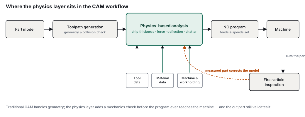
Physics-based CAM is about bringing more of that machining behaviour into the programming process. Instead of relying only on handbook values, supplier recommendations, stored shop recipes or previous jobs, it uses models of the cutting process to predict how a toolpath is likely to behave before it reaches the machine.
That makes it one of the more important ideas behind AI-assisted CAM solutions (such as CAM Assist), particularly for parts where the risk does not come from drawing a toolpath, but from choosing cutting conditions that are safe, stable and productive.
1. What conventional CAM already does well
A CAM system helps turn manufacturing intent into machine motion. The programmer still makes many of the core process decisions, but the software provides the environment for building, calculating, simulating and posting the machining operations.
In a typical workflow, the programmer defines:
- The machine, setup and stock
- The workholding approach and work coordinate system
- The cutting tools, holders and tool assemblies
- The machining operations, such as roughing, finishing, drilling or profiling
- The geometry to machine and the boundaries to respect
- Stepdowns, stepovers, feeds, speeds and entry moves
- Clearance heights, linking moves, retracts and safety regions
- Coolant use, tool changes and post-processing requirements
Once those inputs are defined, the CAM system calculates the cutter’s motion. That calculated path is the toolpath: the route the cutter follows through space as it approaches the part, removes material, links between regions and retracts safely.
This is a major achievement. Modern CAM systems can calculate toolpaths for very complex parts, including multi-axis components that would be almost impossible to program manually. They also help programmers see obvious problems before running the job, such as gouges, collisions, excess stock, missed material or unsafe retracts.
However, a CAM simulation is usually strongest at geometric questions. It can show whether the cutter appears to remove the intended material and avoid the part, holder or fixture. It does not always answer the physical questions that decide whether the process will perform well on the machine.
Those physical questions include:
- How thick is the chip at each point in the cut?
- How much cutting force will be generated?
- How much will the tool bend?
- Will the workpiece move under load?
- Is the tool likely to chatter at the chosen spindle speed?
- Will a corner or slot create a sudden overload?
- Does the selected tool length contribute too much deflection?
- Are the cutting conditions still sensible as engagement changes along the path?
In conventional CAM workflows, many of these questions are answered outside the software. They sit in the programmer’s experience, the machinist’s ear, the tooling catalogue, the shop’s proven recipes and the adjustments made after the first run.
Physics-based CAM tries to move more of that reasoning upstream, into the programming stage.
2. How feeds and speeds are chosen today
Feeds and speeds are often described as if they come from a simple formula. In reality, programmers usually build them from a mixture of data, experience and judgement.
The starting point might be a tooling supplier’s recommendation. A catalogue or online calculator may provide a surface speed, feed per tooth, axial depth of cut and radial engagement for a given tool and material. Those values are useful, but they are rarely the final answer.
A programmer may also look at:
- Previous jobs that used the same material or cutter
- Internal shop standards
- Values stored in a CAM tool library
- Recommendations from a tooling representative
- Cutting data from a handbook or manufacturer’s guide
- Notes from machinists who have run similar parts
- The known behaviour of a specific machine tool
The programmer then adjusts the numbers for the actual job. A short, rigid tool in a stable holder can run very differently from the same cutter with a long stick-out. A heavy slot can load the tool differently compared with a light side cut. A thin wall may need a gentler finishing strategy than a solid block of material. A machine with limited rigidity may need a more conservative approach than a newer, stiffer machine.
Common corrections include:
- Reducing feed or engagement for long-reach tools
- Reducing radial engagement in slots, corners or heavy cuts
- Adjusting spindle speed to avoid chatter
- Leaving more stock before finishing a thin-walled feature
- Changing operation order to keep material in place for support
- Using lighter stepovers on thin walls
- Reducing cutting load for less rigid setups
- Changing strategy when chips are likely to pack or recut
- Applying more conservative parameters for an unfamiliar material
This process works because experienced programmers and machinists understand risk. They know when a number is technically allowed but unwise. They know when a toolpath looks fine in CAM but sounds wrong at the machine. They also know when to ignore an over-aggressive recommendation because the actual setup will not support it.
The weakness is consistency. Much of the reasoning is implicit, and implicit knowledge is hard to scale across teams, shifts, machines and sites. It is also hard to transfer from one programmer to another. If the person who knows the material, machine or fixture is unavailable, the process can become more conservative, more trial-and-error driven, or both.
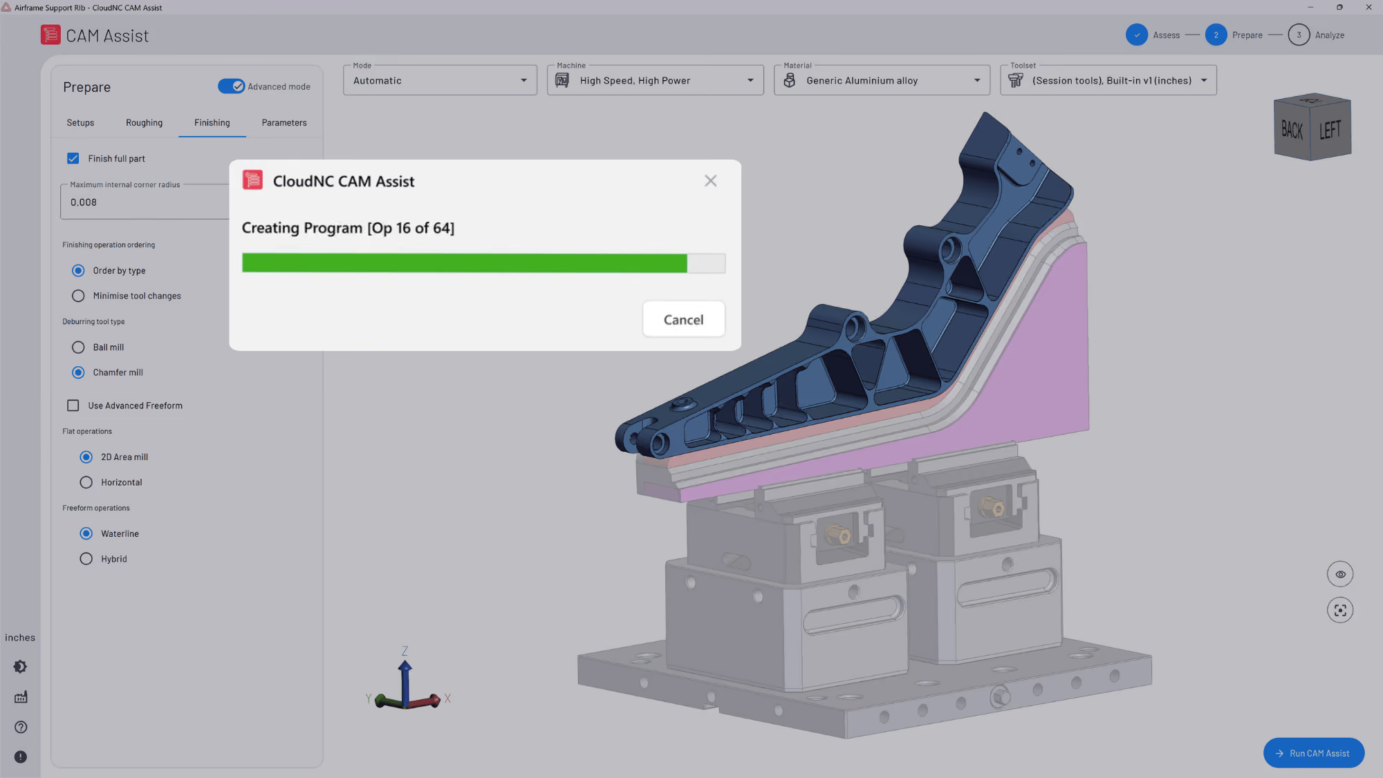
Physics-based CAM is valuable because it gives software a more explicit way to reason about the same issues. Here's our Cutting Parameters Explorer module in action:
3. The three computational approaches behind CAM recommendations
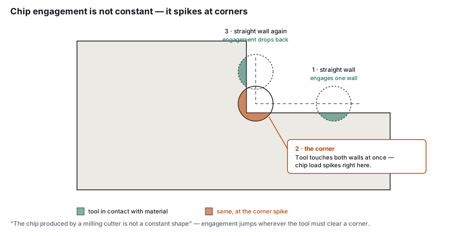
A lot of modern software uses similar language: AI, optimisation, intelligence, automation, smart feeds and adaptive machining. Those labels can blur three very different approaches.
Lookup tables and rules
The most basic approach is a database of recommended values. The system looks at the tool, material and operation type, then returns a feed, speed and depth of cut. It may also apply rules such as reducing engagement for slotting, lowering feed for a long tool, or using a more conservative value for difficult materials.
This approach is useful when the job matches the assumptions behind the table. It is fast, familiar and often good enough for standard work. Many shops use some version of this, whether it lives in CAM, a spreadsheet, a tooling catalogue or a programmer’s own notes.
The limitation appears when the cutting condition is outside the table. A lookup value does not necessarily know that the tool is unusually long, the wall is thin, the corner engagement is about to spike, or the machine-fixture system is less rigid than expected. Rule-based corrections can help, but they are still approximations.
Empirical AI and learned recommendations
The second approach uses historical data. A system may learn from previous programs, tool choices, feeds, speeds, edits and outcomes. This can be powerful when there is enough relevant data, particularly in a production environment where similar parts are made repeatedly.
An empirical system can capture patterns that are hard to write down manually. For example, it may learn that a certain family of parts tends to need conservative finishing passes, or that a certain tool performs well in a certain material on a certain machine.
Its weakness is extrapolation. If the next job is meaningfully different from the jobs in the training data, the system may still produce a confident recommendation. The question is whether that recommendation is grounded in the mechanics of the cut, or mainly in similarity to previous examples.
Physics-based modelling
A physics-based approach starts from the mechanics of machining. It analyses the interaction between the cutter, material, toolpath, machine and workholding. Rather than relying only on what has worked before, it tries to predict what the cut will do.
That prediction may include chip thickness, cutting force, tool deflection, part deflection and dynamic stability. The strongest systems evaluate these conditions locally along the toolpath, because the load on the cutter can change from one region to the next.
In practice, many good systems combine all three approaches. Tables are still useful. Historical data is still useful. Programmer experience remains essential. The important distinction is where the critical recommendation comes from. If a product claims to be physics-based, it should be able to explain the physical reason behind a feed, speed, engagement or strategy change.
4. What physics-based CAM actually models
A serious physics-based CAM system needs to model more than surface speed and feed per tooth. Those values matter, but they are only the start of the cutting process.
The core modelling problem is local. At each point in the toolpath, the software needs to understand what part of the cutter is engaged, how the material is being removed and how the tool, workpiece and machine are likely to respond.
Chip thickness and engagement
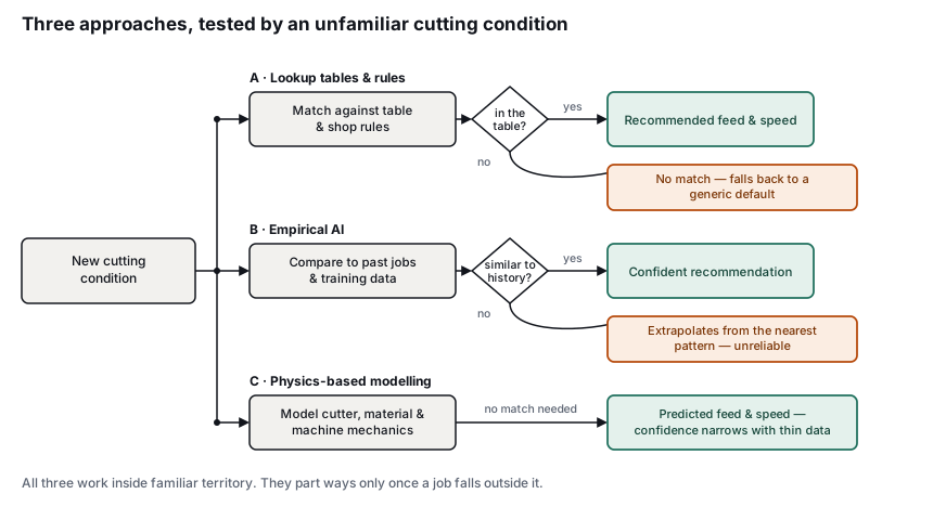
The chip produced by a milling cutter is not a constant shape. It changes as the tool rotates, as radial engagement changes, and as the cutter moves through corners, slots, rest-material regions and variable-engagement paths.
A simple feed-per-tooth value does not fully describe what is happening at the cutting edge. The more useful question is how much material each tooth is actually taking at a given point in the toolpath.
That matters because chip thickness is connected to force, heat, tool wear and stability. A toolpath that looks smooth in CAM can still create a local overload if the cutter engagement rises suddenly. This often happens in corners, full-width cuts, narrow pockets and transitions between light and heavy engagement.
Physics-based CAM should therefore evaluate engagement along the path, rather than treating the whole operation as one uniform cut.
Cutting force
Once chip thickness and engagement are understood, the system can estimate cutting forces. This requires material-specific data, because different materials resist cutting in different ways. Aluminium, stainless steel, titanium, nickel alloys and hardened steels do not behave the same way, and even the same named material can vary by grade, heat treatment and condition.
A useful model should be clear about the material data it is using. Measured cutting data is stronger than a broad material label. A system can still make a sensible estimate when exact data is missing, but the uncertainty should be visible to the programmer.
Cutting force matters because it affects almost everything else in the process. It drives tool deflection, part deflection, spindle load, heat generation, tool wear and vibration risk.
Tool and part deflection
Cutters bend under load. The amount depends on the force, tool diameter, stick-out, holder, tool geometry and overall system stiffness. A short tool in a rigid setup may deflect very little. A long-reach tool cutting deep inside a pocket can deflect enough to affect accuracy, finish and tool life.
The workpiece can also move. This is especially important when machining thin walls, ribs, floors and lightly supported features. A finishing pass may look correct in CAM, but if the wall moves away from the cutter and springs back after the tool has passed, the final part may not match the programmed geometry. (Here's a great example, captured in super slo-mo in our own factory:)
Physics-based CAM can help by predicting when cutting loads are likely to produce too much displacement. In some cases, that may lead to lower engagement. In others, it may suggest a different sequence, leaving support material in place for longer, or finishing both sides of a feature more evenly.
Dynamic stability and chatter
Chatter is a dynamic instability. It depends on the cutter, holder, spindle, machine structure, material, tool length and cutting conditions. Reducing feed may help in some cases, but chatter is not simply a feed-rate problem. Sometimes a different spindle speed, engagement or tool length produces a more stable result.
Stability-lobe analysis is one way to reason about this. In simple terms, it helps identify combinations of spindle speed and depth of cut that are more or less likely to excite vibration. The practical value is that a physics-based system can guide the programmer away from unstable regions and toward more stable cutting conditions.
This is also where modelling has to be honest. Machine dynamics vary, and a software model may not know the exact condition of every spindle, holder, fixture and tool assembly unless those have been measured. A credible system should make its assumptions clear.
Adjacent process risks
Some important machining problems are harder to capture in a clean physics model. Chip evacuation, coolant access, built-up edge, thermal growth, tool wear progression and burr formation can all affect the real process.
A physics-based CAM system may account for some of these, depending on its scope. Where it does not, it should still help the programmer identify areas of risk. For example, high engagement in a pocket with poor chip evacuation may need a different strategy even if the force calculation itself looks acceptable.
The main point is that “physics-based” should mean the software is reasoning from the mechanics of the cut, not simply applying a percentage adjustment to a lookup value.
5. Where physics-based CAM changes programming decisions
The value of physics-based CAM is easiest to see in jobs where the usual rules of thumb become unreliable.
Long-reach roughing
A deep pocket often forces the programmer to use a longer tool than they would like. The tool may be capable of reaching the material, but reach and rigidity are different issues.
In a conventional workflow, the programmer may derate the cut based on experience. That protects the tool and part, but it can also leave productivity on the table. The derating may be too conservative in some areas and too aggressive in others.
A physics-based system can evaluate the combination of tool stick-out, cutter engagement, material and cutting force along the path. It can reduce load where deflection risk is high and allow more productive cutting where the toolpath is stable. The result should be a more consistent decision across the operation, rather than a single conservative value applied everywhere.
Thin-wall finishing
Thin features create a different problem. The cutter may be rigid enough, but the part may not be. A wall, rib or floor can move during cutting, then relax after the tool has passed. That can lead to dimensional error even when the programmed path is geometrically correct.
A physics-aware approach can help the programmer choose finishing conditions that reduce part movement. That may involve smaller stepovers, lighter radial engagement, different stock-to-leave values, or a different machining sequence. The aim is to reduce the chance of discovering the problem only at inspection.
Variable-engagement toolpaths
Many modern toolpaths are designed to control engagement, but real engagement still changes. Corners, slots, rest material, islands and transitions can all create local increases in cutting load. In 5-axis machining, the contact point on the tool can also change as the tool orientation changes.
A single feed and speed value may be reasonable for one region of the toolpath and poor for another. Physics-based CAM can analyse those local changes and adjust the recommendation accordingly. This is particularly useful when the same operation contains both light cutting and heavy contact.
Unfamiliar materials
When a shop cuts a familiar material on a familiar machine, historical knowledge carries a lot of weight. New materials are different. A programmer may have supplier data or a recommendation from a tooling rep, but less confidence about how the material will behave in the actual setup.
Physics-based CAM can improve the starting point if it has relevant material data. It can also expose a data gap when it does not. That second case is important. A system that admits uncertainty is more useful than one that produces a precise-looking number without a strong basis.
6. What physics-based CAM still leaves to the programmer and machinist
Physics-based CAM should narrow the gap between programming and machining, but the gap does not disappear. A model can improve the starting point, flag risky regions and help programmers make better decisions, but the real process still has variables that are difficult to know perfectly in advance.
Several limits are worth keeping explicit:
- First-article inspection still matters. A better model can reduce trial and error, but it cannot remove the need to prove the process on real parts.
- Workholding is hard to model completely. Fixture stiffness, clamping force, stock variation and unsupported features can change how the part behaves.
- Material data can be incomplete. Physics-based recommendations are strongest when the material model matches the actual grade, condition and cutting behaviour.
- Machine condition matters. Spindle health, holder condition, tool runout, axis behaviour and maintenance history can all influence the cut.
- Tool wear changes the process. A fresh cutter and a worn cutter do not generate the same forces or finish.
- Chips and coolant can dominate certain operations. A force model may look acceptable while chip packing or poor coolant access creates a practical problem.
- Machinist judgement remains essential. Sound, vibration, chip colour, surface finish and tool wear all provide feedback that software may not fully capture.
This is why the best use of physics-based CAM is as a decision-support layer inside the programming workflow. It helps the programmer make a better initial choice and gives the machinist a process that is more likely to behave as expected. (Here's how our Strategy Editor works, in exactly this fashion:)
The credible claim is not a perfect prediction across every material, fixture and machine. The credible claim is better reasoning before the first cut.
7. How to evaluate a physics-based CAM claim
Many vendors now describe their CAM or machining software as intelligent, AI-powered or physics-based. The label is less important than the questions behind it.
A practical evaluation should focus on whether the system can explain its recommendations in machining terms. If a feed rate changes, why did it change? If the software reduces engagement in one region but not another, what physical condition drove that decision? If the system recommends a different spindle speed, is it responding to cutting data, stability, tool loading or a rule of thumb?
Useful questions include:
- What physical quantities does the system calculate?
Look for chip thickness, engagement, cutting force, deflection and stability. A feeds-and-speeds table with percentage corrections may still be useful, but it should not be confused with a physics engine. - Where does the material data come from?
Ask whether the system uses measured cutting data, supplier data, internal testing, broad material families or user-defined values. Also ask how it handles missing or uncertain material data. - How does it handle stiffness?
Tool stick-out, holder geometry, cutter diameter, part flexibility and workholding all influence the result. A system that ignores stiffness will struggle with many of the situations where physics matters most. - How does it account for chatter or dynamic stability?
The answer does not need to promise perfection, but it should show that the software understands stability as a dynamic problem rather than treating it as a simple feed-rate issue. - What does the system refuse to claim?
Strong vendors are usually clear about their limits. Be cautious of any product that claims reliable first-part success across all materials, fixtures and machines without explaining what it can and cannot know.
At CloudNC, the practical test is whether the recommendation can be connected to the physical cut. A good trial should use a real part, a real setup and a decision that currently relies on expert judgement. Good candidates include a deep pocket, a long-reach tool, a thin wall, a difficult material or a 3+2-axis operation with changing engagement.
The point of the trial is not to see whether the software can produce an impressive demo. The point is to compare its recommendations with what an experienced programmer would do, what the machine accepts and what inspection shows after the cut.
Closing: the test is still at the spindle
Physics-based CAM is best understood as an additional layer of machining intelligence inside the programming process. Conventional CAM helps programmers define operations and calculate tool motion. Lookup tables and rules help provide starting values. Empirical systems learn from previous jobs. Physics-based systems add models of the cut itself.
The most important mechanisms are chip thickness, cutting force, deflection and stability. When those are modelled well, the software can make better recommendations about feeds, speeds, engagement and strategy. When they are missing, the system may still be useful, but the claim of being physics-based becomes weaker.
The final test remains practical. Can the software explain why it changed the machining decision, and does that explanation hold up when the part is cut?
That is where physics-based CAM earns its place: not in the label, but in the quality of the decision at the spindle.