Cycle time rarely disappears in one dramatic programme edit. More often, it leaks away through dozens of small decisions: a clearance plane set higher than necessary, a drill pecking when it could run in one pass, a tool called twice or a roughing strategy that does not suit the feature.
Those seconds matter in production. Saving one minute on a 500-part order releases 8 hours and 20 minutes of machine capacity.
For teams working out how to reduce cycle times for CNC machining, the starting point is the complete process. That includes loading, probing, cutting, rapid positioning, tool changes, inspection and unloading. The best results usually come from reducing several smaller sources of delay while keeping the process safe, stable and repeatable.
What CNC cycle time includes
Some shops measure cycle time from cycle start to the end of the CNC programme. That is a useful machine-based figure, but it may exclude recurring work around the machine.
For a practical cycle-time review, record:
- Loading and unloading
- Work offset setting and probing
- Cutting time
- Rapid, linking and positioning moves
- Tool changes
- In-cycle inspection
- Chip clearing
- Recurring operator actions
First-off programming and setup time can be tracked separately. Any task repeated for every component belongs in the per-part calculation.
Use the same measurement method before and after a change. CAM estimates, control timers and stopwatch readings can differ, so make the baseline clear. On a production job, time several consecutive parts rather than choosing the quickest cycle of the shift.
1. Measure a real production cycle
Choose a job where the result will matter. A repeat part with high annual volume, a long cycle or a poor margin is usually a better candidate than a one-off component.
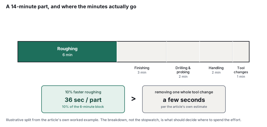
Break the cycle into meaningful stages. A 14-minute part might contain six minutes of roughing, three minutes of finishing, two minutes of drilling and probing, one minute of tool changes, and two minutes of handling.
That breakdown points the team towards the largest opportunity. A 10 per cent improvement to a six-minute roughing operation is worth far more than saving one second on a single tool change.
Useful evidence includes:
- Actual machine time
- CAM-estimated time
- Time spent cutting air
- Spindle load during major operations
- Tool life and reason for replacement
- Scrap and rework
- Dimensional and surface-finish results
- Operator interventions
Video can be useful on short, repetitive jobs. It often reveals pauses, double handling and unnecessary movement that are easy to overlook while the operator is running several machines.
2. Reduce non-cutting movement without losing collision safety
Non-cutting movement can offer useful savings, but it should only be shortened after the complete setup has been represented accurately.
The CAM environment should contain the stock, vice or fixture, clamps, jaws, bolts, tombstones and any other object the tool or holder could reach. Tool assemblies also need realistic holder geometry and gauge lengths. Where possible, simulation should show the stock as it exists at that point in the process, rather than assuming that every earlier operation has already cleared the area.
A height that clears the finished component may still place the holder into a clamp. A linking move that appears safe above the model may cross stock that has not yet been removed. This is why modelled workholding is essential when trimming rapid and retract movements.
Understand how the machine executes rapid moves
The path shown by a backplotter will only reflect reality when its motion assumptions match the machine and control.
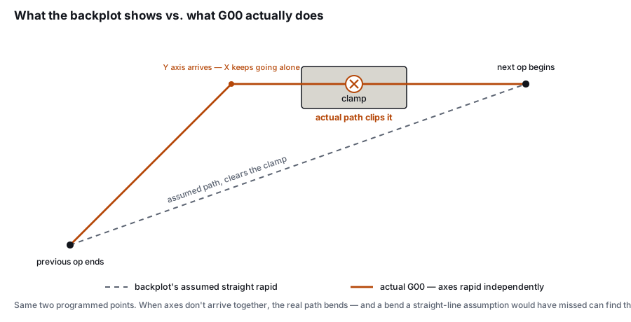
G00 behaviour varies. On some machines, the axes are coordinated along a straight path. On others, each axis moves at its own rapid rate and may arrive at the destination at a different time. The resulting tool movement can follow a non-linear or dog-leg path between the programmed points.
For example, the Haas documentation for G00 rapid motion explains that rapid movement will not generally follow one straight line and that the axes may complete their movements at different times. By comparison, the Haas documentation for G01 linear movement states that the programmed axes reach their destination together. Other controls can offer linear or non-linear rapid interpolation modes, depending on the machine configuration.
Where the actual G00 path creates uncertainty, possible approaches include:
- Separating the Z movement from the X and Y movement
- Using a suitable high-feed G01 move in a critical area
- Using a control-specific linear rapid function
- Adjusting the CAM post to reflect the machine’s known behaviour
- Retaining a higher local clearance around clamps and remaining stock
These choices are machine and control specific. A high-feed G01 may be slower than a true rapid, but it can provide an interpolated path that agrees more closely with the programmed line. It should only be used where the machine, post and shop procedures support it.
Some controls also have parameters that affect rapid interpolation. These may be machine-builder or servo-level settings rather than everyday programming options. Confirm them with the machine builder or an authorised service provider instead of treating them as a quick shop-floor adjustment.
Once the setup and motion behaviour are understood, review:
- Global clearance heights that could become local clearances
- Full retracts between nearby features
- Long lead-ins and lead-outs
- Repeated returns to the same point
- Links that pass over already cleared areas
- Dwell commands left over from prove-out
- Toolpaths that recut cleared stock
- Tools called more than once without a process reason
Prove out every revised movement using the shop’s normal safety process, including simulation, single block, reduced rapid override and visual confirmation where appropriate.
3. Match the roughing strategy to the feature, material and tool
High efficiency milling, adaptive clearing and dynamic milling can remove material quickly while maintaining relatively consistent cutter engagement. They generally combine a light radial depth of cut, a deeper axial cut and a feed rate adjusted for chip thinning.
These strategies are especially useful when conventional toolpaths would repeatedly bury the cutter in corners. They can also work well in harder materials and alloys prone to work hardening, where stable engagement and correct chip thickness help control heat, rubbing and sudden load changes.
CloudNC’s guide to high efficiency milling covers the basic relationship between radial engagement, axial depth and chip thickness. The Harvey Performance introduction to trochoidal milling also explains the advantages, along with the machine, software and tooling limitations that need to be considered.
Watch for narrow slots and small cutters
A trochoidal path travels farther than a direct slotting path. In a reasonably large pocket, the higher feed and deeper axial cut can more than compensate for that extra distance. As the feature becomes narrower, the repeated looping motion can take longer than a simpler strategy.
Small tools add another constraint. They have less core strength and are more sensitive to runout, vibration and uneven loading. Chip-thinning compensation may produce a high programmed feed, but the cutter and machine still need enough rigidity and acceleration to achieve it reliably.
In that range of feature size and tool diameter, a full-width ramp, a direct slotting operation or a cutter designed specifically for full slotting may finish sooner. The result depends on the material, slot depth, cutter geometry, machine dynamics and chip evacuation.
The Practical Machinist comparison of dynamic and traditional toolpaths provides a useful demonstration. It compares several solid carbide and indexable tools rather than assuming the dynamic toolpath will always be quickest.
Compare HEM with high-feed and indexable tooling
High-feed mills use shallow axial cuts, small entering angles and high feed per tooth. On suitable features, a high-feed mill following a relatively simple path can outperform a standard end mill running a long adaptive toolpath.
Indexable end mills may also achieve higher material removal rates on machines with the power and rigidity to use them. They can be particularly attractive when the operation allows a larger diameter tool and the cost per cutting edge matters.
For open, accessible areas, a face or shell mill can remove stock much faster than clearing the same surface with a smaller end mill. Sandvik Coromant’s high-feed milling guidance describes the productivity advantages of small entering angles, while its face milling guide explains how cutter choice changes with depth of cut, stability and surface requirements.
When selecting a roughing strategy, compare:
- Actual machine time
- Material removal rate
- Tool life
- Tool cost per component
- Spindle load
- Machine acceleration and control performance
- Chip evacuation
- The need for rest machining
- The remaining finishing allowance
A shorter CAM simulation is useful evidence, but it is not the final result. Run the most promising options on the machine and compare complete, stable cycles.
4. Tune cutting data with evidence
Feeds and speeds are obvious cycle-time levers, although simply increasing the feed override rarely provides a durable answer.
Start with toolmaker data and identify the current constraint. That might be spindle power, chatter, tool deflection, workholding, chip evacuation, coolant delivery or machine acceleration.
Review:
- Actual chip thickness
- Spindle load
- Tool wear pattern
- Chatter and vibration
- Chip shape
- Coolant direction and pressure
- Part movement
- Surface finish
- Feature deflection
- Machine power and torque
Change one meaningful variable at a time. Depending on the operation, this might be feed per tooth, spindle speed, radial engagement, axial depth or cutter geometry.
Pay particular attention to chip-thinning compensation. A light radial cut requires a higher programmed feed to maintain the intended maximum chip thickness, but that feed must remain realistic for the tool and machine. Short moves and tightly curved paths may never reach the programmed value because the machine spends much of the operation accelerating and decelerating.
Record cycle time alongside tool life and quality. A two-minute saving is quickly lost when the revised cut causes an extra tool change, poor finish or rework.
CloudNC’s article on setting CNC cutting parameters provides more detail on balancing cycle time, tool loading and process limits.
5. Improve rigidity before asking the tool to go faster
A weak setup forces conservative cutting data. Better rigidity can release cycle time without a major change to the overall machining method.
Use the shortest practical tool stick-out, a suitable holder and the largest cutter diameter the feature allows. Keep clamping close to the cutting area and support thin or flexible sections where possible.
Workholding deserves the same attention. Well-designed soft jaws, modular fixtures and repeatable zero-point systems can improve stability while reducing recurring setup work. They also make the conditions behind the proven cutting data easier to reproduce.
There is often a trade-off between access and rigidity. A long-reach cutter may avoid a second setup, but its lower stability can slow every pass. A second operation with a short, rigid tool may produce a shorter total process.
6. Reduce tool changes and repeated operations
A single tool change may only take a few seconds. A programme with many repeated or unnecessary changes can give away a significant amount of capacity over a production batch.
Check whether one tool can complete several related operations without weakening the process. Depending on the tolerances and tool design:
- One end mill may rough and finish non-critical features
- A combination tool may drill and chamfer
- A suitable drill may remove the need for spot drilling
- A face mill may rough and finish a broad surface
- One tool may machine several parts before the next tool is called
Operation order matters too. Grouping work by tool can reduce repeated calls, particularly when several components are held in one fixture.
Preset tools away from the machine and keep proven assemblies ready for repeat jobs. A machine should not be waiting while someone searches for a holder, builds a tool assembly or measures a replacement.
Tool consolidation still needs judgement. A dedicated finishing tool may protect surface finish, size control and predictable tool life. Measure the saving against the risk rather than removing tools for the sake of a shorter tool list.
7. Shorten drilling cycles with the right drill and retract logic
Hole-making can contain more avoidable motion than many programmers expect. Spotting, pecking and retracting to a high clearance plane are often inherited from an earlier programme without being reconsidered for the current tool and setup.
Assess solid carbide drilling for production work
For a rigid machine making hundreds or thousands of the same holes, solid carbide should be the baseline against which HSS is justified.
HSS remains useful on low-volume work, less rigid machines and some awkward applications. On stable production work, however, using HSS simply because it is familiar can add spotting, pecking, slower penetration rates and more frequent tool changes.
Many modern solid carbide drills can enter directly without a separate spot-drilling operation when the drill design, entry surface and accuracy requirement allow it. They may also drill in one pass without pecking when hole depth, coolant supply and chip evacuation are suitable.
Pecking should solve a real chip-control problem. Repeatedly withdrawing and re-entering the hole adds cycle time and can increase tool wear. Harvey Performance’s carbide drill guidance recommends using peck cycles only when the application needs them. Its guide to HSS, cobalt and carbide drill substrates provides further detail on choosing the right substrate.
Before removing the spot or peck operation, verify:
- Toolmaker recommendations
- Entry angle and surface condition
- Drill runout
- Holder rigidity
- Hole depth-to-diameter ratio
- Coolant pressure and flow
- Chip shape and evacuation
- Hole position, size and finish
- Exit conditions and burr requirements
For high-volume work, compare cost per finished hole rather than purchase price per drill. A more expensive carbide drill can be considerably cheaper when it shortens the cycle and lasts for more components.
Use local retract heights between groups of holes
The clearance needed to cross a clamp does not need to be used between every hole.
Consider a row of ten holes divided by clamps. The drill may only need a low retract plane while moving between the first three holes. It can then return to a higher plane to cross the clamp, drop back to the lower retract height for the next group and repeat the sequence.
On controls using the familiar G98 and G99 canned-cycle behaviour, G99 returns the drill to the R plane while G98 returns it to the higher initial point. The Haas G98 documentation shows this exact type of move over a toe clamp, and Haas also provides a practical guide to G98, G99 and R planes. Control behaviour and syntax vary, so verify the method for the specific machine.
This local approach avoids lifting above the highest clamp after every hole. On a plate containing dozens or hundreds of holes, the saving can be substantial.
The same principle applies to probing. Review duplicated measurements, distant approach points and repeated checks that do not change the control’s next decision. Keep the inspection that protects the process and remove movement that adds no information.

8. Cut the number of setups
Every re-clamp adds handling, probing and another opportunity for variation.
Where the part and equipment allow it, combining operations can shorten the cycle and reduce total lead time. Options include:
- Machining more faces in a 3+2 setup
- Using a fourth-axis fixture
- Holding several parts at once
- Designing soft jaws for better access
- Moving a secondary feature into the main operation
- Using probing to maintain a common datum
CloudNC’s article on breaking a part out in one 5-axis operation discusses the benefits and trade-offs in more detail.
Fewer setups do not guarantee a faster process. Indexing, longer tools, complicated fixtures and restricted chip clearance can absorb the saving.
9. Simulate the real setup and verify the actual cycle
Simulation is most useful when it represents the complete machining environment.
Include the machine, stock, tool assembly, fixtures and clamps. Use in-process stock where the CAM system supports it so that links are checked against the material that actually remains.
Machine simulation should also reflect the post and control behaviour. A backplot showing a clear straight line does not prove that the machine will execute G00 along that line. Control-specific rapid behaviour, rotary unwinding, tool-change positions and machine limits all need consideration.
Once the revised programme reaches the machine, use the shop’s normal prove-out procedure. Monitor:
- Spindle load
- Sound and vibration
- Chip evacuation
- Tool wear
- Part movement
- Dimensions
- Surface finish
- Actual cycle time
Compare the machine time with the CAM estimate. A large gap may point to acceleration limits, control processing, spindle ramp time, tool-change behaviour or optional stops that the CAM estimate does not model fully.
Keep a brief change record showing what was altered, the reason, the previous cycle time, the new cycle time and any effect on tool life or quality. That record makes a successful change repeatable and an unsuccessful trial easy to reverse.
10. Standardise the best-known process
A cycle-time improvement can disappear when the next shift loads an old programme or builds the tool differently.
Store the approved programme revision with:
- The correct setup sheet
- Tool and holder details
- Gauge lengths
- Fixture information
- Work offsets
- Inspection requirements
- Proven cutting data
- Expected cycle time
- Photographs where they remove ambiguity
For repeat parts, maintain one controlled best-known programme. Avoid relying on copies held on individual machines or in personal folders.
For part families, capture reusable methods for tool selection, workholding, roughing and clearance management. Leave room for the programmer to account for differences in geometry, material and machine capability.
Revisit the process when tooling, batch size, material or machine changes. A proven programme is a strong starting point, although its assumptions still need to match the next production run.
Where CAM programming fits
Programming time and machine cycle time are different measurements, but they influence one another. A rushed CAM programme may contain conservative defaults, high global clearances, duplicated operations or a roughing strategy carried over from a different part.
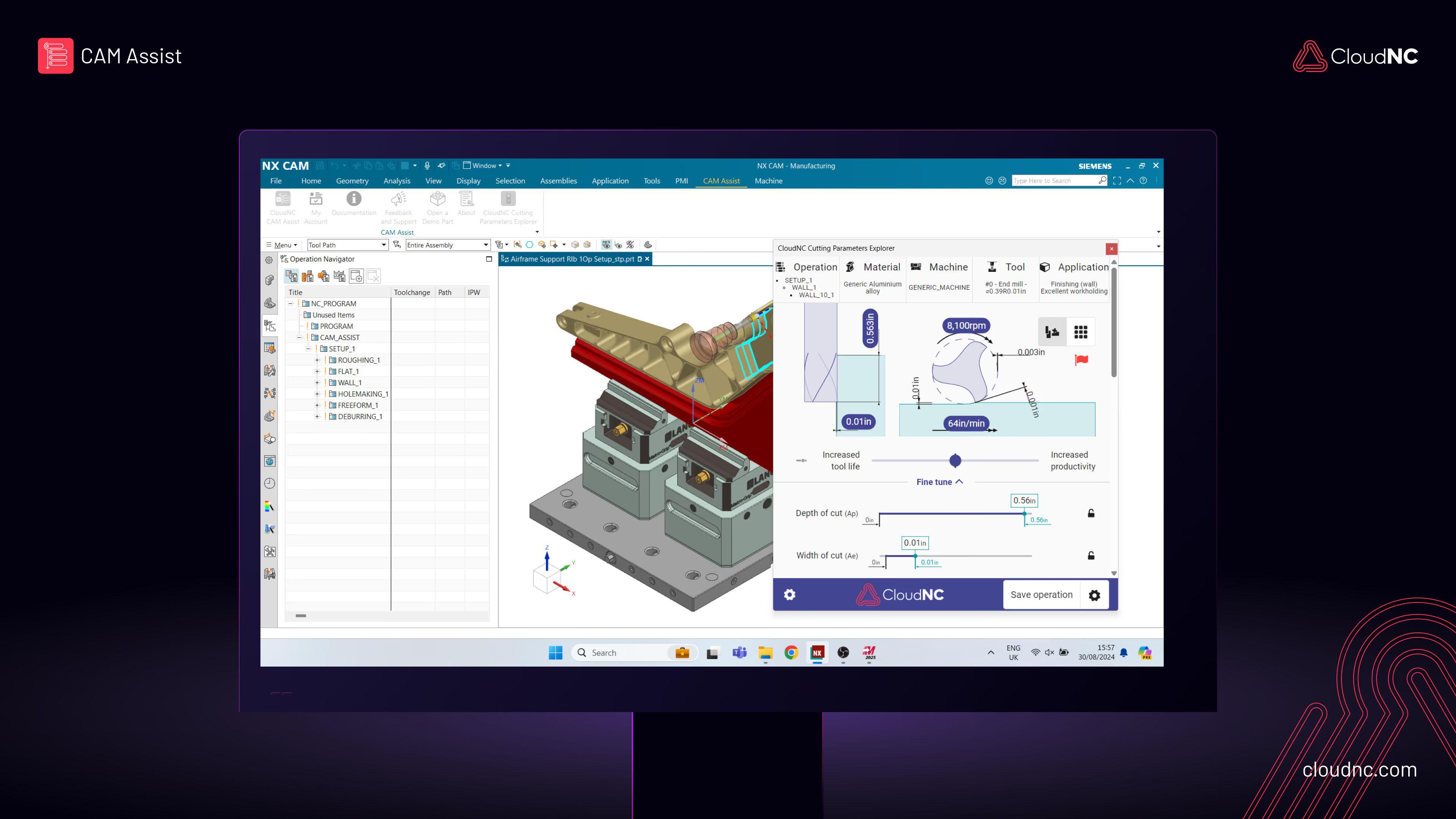
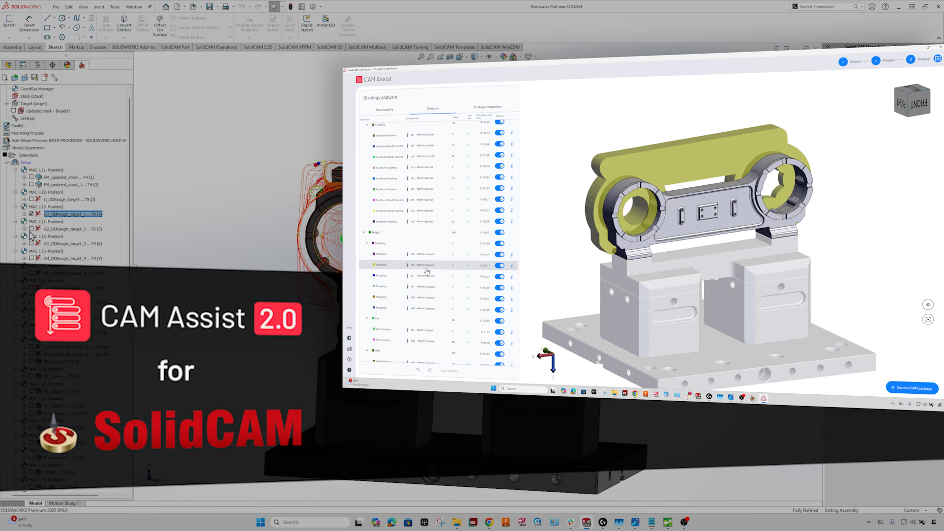
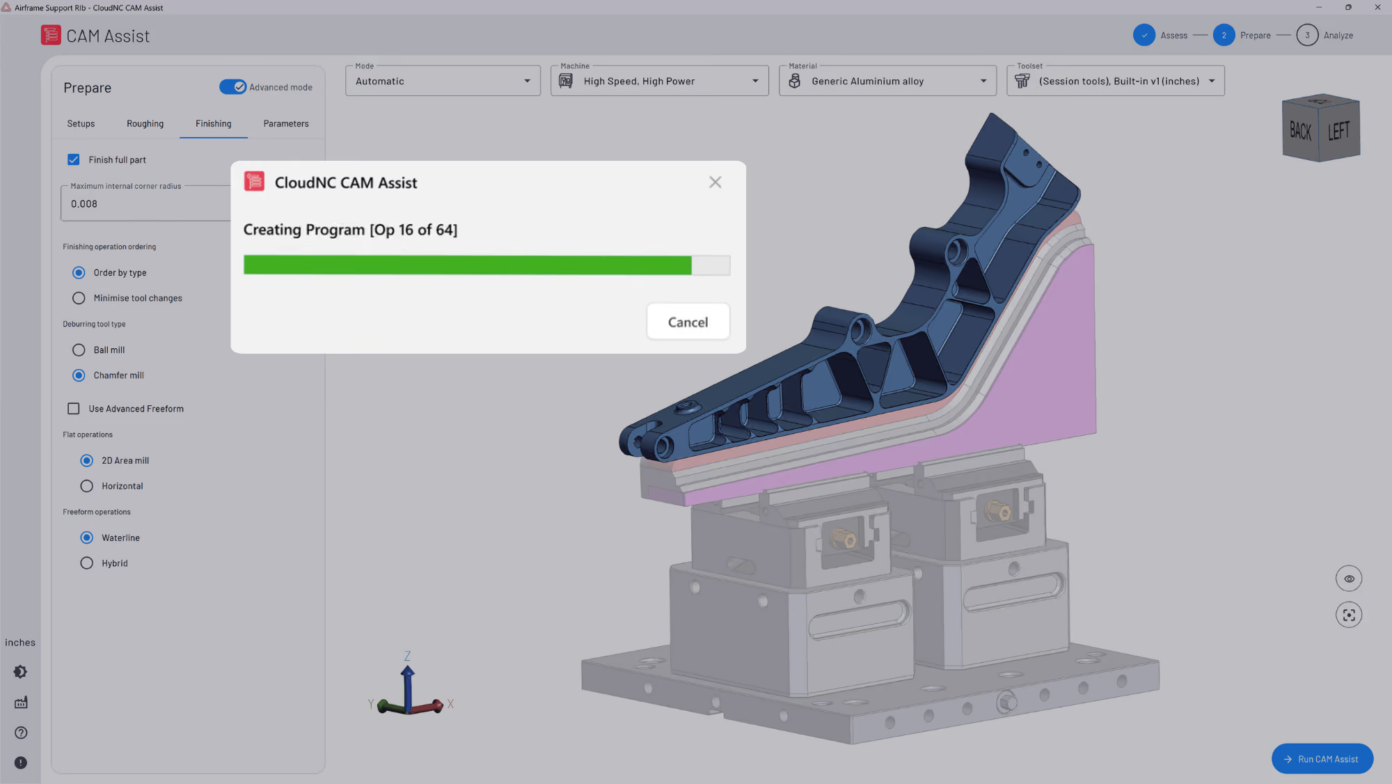
CAM Assist can generate machining strategies and toolpaths within existing CAM workflows, giving programmers a faster starting point for many milling jobs. The programmer can then concentrate on the details that determine real machine performance, including workholding, tool selection, cutting data, rapid behaviour, simulation and prove-out.
For a broader view of spindle availability, CloudNC’s guide to increasing CNC capacity without buying new machines covers programming, setup, scheduling and machine utilisation together.
Calculate the value of a shorter cycle
Use a simple capacity calculation:
Annual machine hours released = seconds saved per part × annual quantity ÷ 3,600
Saving 45 seconds on a component produced 12,000 times releases 150 machine hours a year.
Those hours might support additional orders, shorter lead times, fewer late shifts or more planned maintenance. Their commercial value depends on what the machine can produce with the released time.
This calculation also helps with prioritisation. A modest improvement on a high-volume component can be worth more than a dramatic reduction on a part made twice a year.
Final takeaway
The most reliable cycle-time gains come from understanding what the machine is doing throughout the whole process.
Measure the actual cycle. Model the workholding before lowering clearances. Confirm how the control executes rapid moves. Compare HEM with full-slotting, high-feed, indexable and face-milling options. Review whether carbide drilling can remove spotting and pecking. Use high clearance only where the setup requires it.
Then prove the change on the machine and check the result against quality, tool life and process stability.
A minute rarely disappears in one place. It is usually spread across a dozen small decisions, repeated on every part. Fix enough of them and the released capacity becomes significant.