CAM software is used by manufacturers to plan how a part will be made on CNC machines. CAM stands for Computer-Aided Manufacturing, and in CNC (Computer-Numerical-Control) machining it sits between the digital part model and the machine tool.
A Computer Aided Design (CAD) model defines the shape of the part. CAM software helps the programmer decide how that shape will be machined: which tools to use and operations to run, how fast the tool should move and where it should cut, and how the finished program should be posted for a specific CNC machine.
As Siemens explains in its definition of computer-aided manufacturing, CAM commonly refers to using NC software to create detailed instructions, often G-code, that drive CNC machine tools. Autodesk gives a similar explanation, describing CAM software for CNC machining as software that converts CAD designs into machine instructions.
That makes CAM one of the most important parts of modern precision manufacturing. It helps manufacturers create toolpaths, simulate machining, reduce mistakes and get from design to finished part with more consistency.
This guide explains what CAM software is, how CAM programming works, and how newer AI-assisted tools are changing the way CNC programmers move from CAD to first cut.
Breaking down CAM
In simple terms, CAM means using software to help manufacture physical parts. In machining, that usually means creating toolpaths and machine instructions for CNC mills, lathes, routers, EDM machines and other computer-controlled equipment.
The phrase has two important parts.
“Computer-aided” means that software supports the manufacturing process. The programmer still makes critical decisions, but the software helps calculate tool movement, cutting parameters, simulation and machine output.
“Manufacturing” means the output is used to make something physical. CAM is not just a design tool. Its purpose is to help move a part from digital geometry into production.
In CNC machining, CAM software is often used to create NC code or G-code, which is what drives the CNC machine. The code needs to match the machine, controller, tooling, workholding and material, which is why CAM programming requires both software knowledge and machining experience.
What is CAM software used for?
CAM software is used to turn a design into a manufacturing plan.
A typical CAM workflow includes:
- Importing or opening a CAD model
- Defining the stock material
- Setting the work coordinate system
- Choosing the CNC machine and setup
- Selecting cutting tools
- Creating roughing, finishing, drilling and other operations
- Generating toolpaths
- Setting feeds, speeds, stepdowns and stepovers
- Simulating the machining process
- Checking for collisions or gouges
- Posting the program for the machine controller
The exact workflow varies by shop, part type and CAM package. A simple 2.5-axis part may need only a handful of operations. A complex aerospace, medical or energy component may need multiple setups, careful tool selection, 3+2-axis positioning or simultaneous 5-axis machining.
The goal is the same in every case: create a safe, reliable and efficient machining process that produces the required part to the required quality.
How CAM software works in CNC machining
CAM software works by taking part geometry and helping the programmer build a sequence of machining operations. Each operation removes material in a controlled way until the finished part matches the design.
Here is a typical CAM workflow.
The programmer imports the CAD model
The process usually starts with a CAD file. This might be a native CAD model, a STEP file, an IGES file or another 3D format.
The CAM programmer reviews the model to understand the features that need machining, such as pockets, holes, bosses, slots, profiles, freeform surfaces and tight-tolerance areas.
The setup is defined
The programmer defines how the part will sit in the machine. This includes the stock material, fixture, workholding method, datum, machine orientation and work coordinate system.
This step matters because every toolpath depends on the relationship between the model, stock, fixture and machine axes. A poor setup can create access problems, long cycle times or collision risks later in the process.
Machining operations are selected
Next, the programmer chooses the operations needed to make the part. Common CAM operations include facing, adaptive clearing, pocketing, contouring, slotting, drilling, tapping, boring, chamfering and finishing.
Each operation has a purpose. Roughing removes bulk material. Semi-finishing prepares surfaces for final passes. Finishing achieves the final shape, tolerance and surface finish.
Cutting tools and parameters are chosen
The programmer selects tools from the shop’s tool library. Tool choice depends on the material, feature size, machine power, reach, rigidity, finish requirement and tolerance.
The programmer also sets feeds and speeds. These control how quickly the tool rotates and how fast it moves through the material. Good parameters help protect the tool, improve surface finish and keep cycle time under control.
Toolpaths are generated and checked
Once the operation is defined, the CAM software calculates the toolpath. This is the path the cutting tool will follow to remove material.
The programmer then reviews the result. They may adjust boundaries, entry moves, linking moves, depths of cut, clearances, tool engagement and finishing passes.
The program is simulated
Simulation lets the programmer check what will happen before the job reaches the machine. This can reveal collisions, gouges, leftover stock, over-travel, inefficient air cutting or toolholder clashes.
Siemens includes machine tool simulation and postprocessing in its broader description of computer-aided manufacturing workflows, which reflects why CAM is so valuable in production environments. It helps catch problems earlier, when they are cheaper and easier to fix.
The code is posted to the CNC machine
The final CAM program is processed through a post processor. The post processor translates the CAM operations into the machine-specific code required by a particular CNC controller.
This is why two shops can use the same CAM package but produce different machine code. The output has to match the machine, controller, kinematics and local shop standards.
CAM vs CAD vs CAE vs CNC
CAM is often discussed alongside CAD, CAE and CNC. The terms are related, but they describe different parts of the digital manufacturing process.
CAD stands for computer-aided design. CAD software is used to create the digital model or drawing of the part.
CAE stands for computer-aided engineering. CAE software is used to analyse and test designs, for example through simulation, stress analysis, thermal analysis or fluid dynamics.
CAM stands for computer-aided manufacturing. CAM software is used to plan how the part will be made.
CNC stands for computer numerical control. CNC refers to the machine control system that follows the programmed instructions to move axes, spin tools, change tools and cut material.
A simple way to think about it is this: CAD defines the part, CAE helps test the part, CAM plans the machining process, and CNC equipment makes the part.
Why CAM software matters
CAM software matters because it helps machine shops produce complex parts with consistency.
Modern CNC machines are capable of extremely accurate movement, but they still need the right instructions. CAM software gives programmers a structured way to create those instructions, test them and adapt them to each job.
The benefits include:
- Shorter programming time
- Better repeatability across similar parts
- Fewer manual coding errors
- Stronger control over cutting strategy
- Earlier detection of collisions and gouges
- Better use of tool libraries and shop standards
- More reliable handoff from design to production
- Improved ability to machine complex 3D geometry
CAM software also helps shops preserve knowledge. Tool libraries, templates, proven strategies and post processors all capture decisions that would otherwise sit only in the heads of experienced programmers.
That matters in a market where skilled CNC programmers are hard to find and lead times are under pressure.
The evolution of CAM software
CAM has changed significantly over time.
Early CNC programs were often written manually, line by line. That required deep knowledge of G-code and machine behaviour. Manual programming still has a place, especially for simple edits and experienced operators, but it becomes impractical for many complex parts.
Graphical CAM systems made it easier to create toolpaths from part geometry. Programmers could interact with the model, define operations visually and generate code more quickly.
Integrated CAD/CAM systems then brought design and manufacturing closer together. A programmer could work from the same digital model used by the design team, reducing translation steps and making changes easier to manage.
More recently, CAM software has added better simulation, tool libraries, cloud collaboration, machine-aware verification and AI-assisted programming. These advances are helping shops reduce repetitive work, improve consistency and give programmers better starting points.
The direction of travel is clear: CAM software is becoming more connected, more intelligent and more closely tied to the real constraints of the machine shop.
What to look for in modern CAM software
The right CAM software depends on the shop, machine mix, part complexity and customer requirements. However, there are several factors worth considering.
Machine support: The CAM package should support your current machines and the types of machining you need, such as 3-axis, 3+2-axis, 5-axis, turning or mill-turn.
Post processors: Reliable post processors are essential. The output must match the machine and controller.
Tool library control: A strong tool library helps standardise programming and reduce repeated setup work.
Simulation and verification: The software should help you find problems before they create scrap, broken tools or machine downtime.
CAD compatibility: Good file compatibility reduces friction when working with customer models.
Ease of editing: Programmers need control. The software should make it straightforward to adjust strategies, parameters and toolpaths.
Support and training: CAM software becomes part of the daily production workflow, so support quality matters.
AI assistance: AI can help with strategy generation, manufacturability feedback and repetitive programming steps, but the programmer should be able to review, edit and approve the output.
Where AI fits into CAM programming
AI is becoming more common in CAM because many programming decisions are pattern-based. A programmer looks at part geometry, material, tools, machine limits and workholding, then chooses a machining approach. AI can help suggest a starting point by analysing similar constraints at speed.
This is especially useful for repetitive tasks, first-pass strategy creation and parts with familiar machining features. The programmer can then review the proposed approach, make adjustments and apply shop-specific judgement.
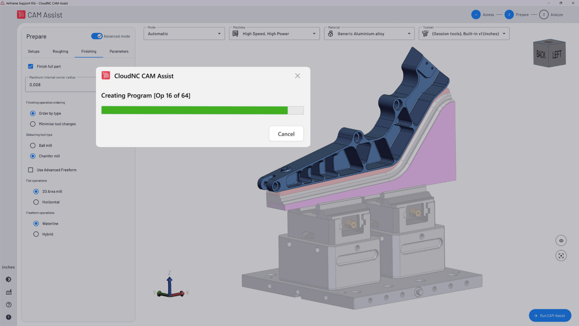
CloudNC’s CAM Assist is one example of this shift. It works inside existing CAM workflows and supports platforms including Autodesk Fusion, Mastercam, Siemens NX, GibbsCAM and SolidCAM. The aim is to help programmers generate machining strategies and toolpaths faster while staying in control of the final program.
In our case study with MSP Manufacturing, a programmer who previously took around 1.5 to 2 hours to program a part used CAM Assist to get 80% of the way there in 7 minutes, then spent 15 minutes fine-tuning the result. That kind of workflow shows where AI-assisted CAM is heading: faster first drafts, human review and more time for high-value machining decisions.
Is CAM software only for CNC machining?
CAM is most closely associated with CNC machining, but it can apply to other manufacturing processes too. CAM software may be used for milling, turning, routing, laser cutting, waterjet cutting, wire EDM, additive manufacturing and hybrid manufacturing workflows.
In each case, the software helps translate a digital design into machine instructions.
However, the details vary widely. A CAM workflow for a 3-axis milling job is very different from a workflow for 5-axis aerospace machining, a mill-turn component or a 3D-printed metal part. That is why specialist CAM knowledge remains important.
Do you need CAM software to run a CNC machine?
A CNC machine needs instructions, but those instructions do not always have to come from CAM software.
For very simple jobs, an operator may write G-code by hand, use conversational programming at the machine control, or make small edits directly on the controller.
For more complex parts, CAM software is usually the practical choice. It allows programmers to work from 3D geometry, create advanced toolpaths, simulate the process and post code for the machine.
Most modern machine shops use CAM because it helps manage the complexity, speed and precision expected in production machining.
The takeaway
CAM software helps manufacturers turn CAD models into CNC machining instructions. It supports the programmer through setup, tool selection, toolpath generation, simulation and post processing.
For anyone learning CAM programming basics, the key idea is simple: CAM software defines how a part will be made. It connects design intent with the physical process of cutting material.
As CAM software becomes more intelligent, the programmer’s role is also evolving. Instead of spending as much time on repetitive strategy creation, skilled programmers can focus more attention on setup quality, manufacturability, process improvement and final program approval.
For machine shops facing tighter lead times and limited programming capacity, that shift matters. The future of CAM is faster, more connected and more practical for the people who need to keep spindles cutting.
To see how AI-assisted CAM can fit into an existing machining workflow, explore CAM Assist by CloudNC or book a CAM Assist demo.
References and further reading
For a neutral industry definition, see Siemens’ guide to computer-aided manufacturing.
For additional context on CAD, CAM, toolpaths and G-code, see Autodesk’s guide to CAM software for CNC machining.
For CloudNC product context, see CAM Assist for Autodesk Fusion, Mastercam, Siemens NX, GibbsCAM and SolidCAM.
For a real-world example of AI-assisted CAM programming, read the MSP Manufacturing case study.